Cisco Single BGP with Multi-hop (load-balancing) on Ethernet using GRE Tunnel
|
|
[Argument]
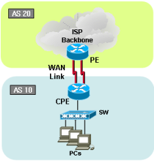
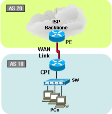
Traffic load-sharing and failover with multi-hop eBGP configuration has been failed in market. Most ISP provides Ethernet based connection services in cost affective way. However, due to characteristic of the Ethernet technology architecture; router/BGP couldn’t find a link is being down. How? Long distance Ethernet service uses transport network in the middle of the path and if the link is down any reason, each end Ethernet segment wouldn’t detect the outage. BGP will keep on sending packet to the dead link. See below solution to cover the issue. In this example, we will use GRE tunnel to achieve our goal.
Key idea: We will make static route points to GRE Tunnel interfaces instead of physical interface which couldn’t detect link down unless it is disconnected
 on Ethernet using GRE Tunnel")
[Traffic flow]
Outbound traffic on CPE perspective
Both circuits will share outbound traffic. It wouldn’t be exact 50/50% of traffic due to traffic will be routed per destination, but not per packets. However, if you want to share links by packet, you can apply command "ip load-sharing" on participant interfaces.
Inbound traffic on CPE perspectiveSame concept as outbound traffic flow
[CPE/Customer Cisco Router]
version 12.4
no service password-encryption
!
hostname CPE
!
boot-start-marker
boot-end-marker
!
no aaa new-model
!
ip cef
!
interface Loopback0
ip address 20.20.20.20 255.255.255.255
!
interface Tunnel1
ip address 10.20.1.2 255.255.255.252
keepalive 5 3
tunnel source FastEthernet1/0
tunnel destination 1.1.1.1
!
interface Tunnel2
ip address 10.20.2.2 255.255.255.252
keepalive 5 3
tunnel source FastEthernet2/0
tunnel destination 2.2.2.1
!
interface Tunnel3
ip address 10.20.3.2 255.255.255.252
keepalive 5 3
tunnel source FastEthernet3/0
tunnel destination 3.3.3.1
!
interface FastEthernet0/0
no ip address
shutdown
!
interface FastEthernet0/1
no ip address
shutdown
!
interface FastEthernet1/0 <———- to ISP WAN Link 1
ip address 1.1.1.2 255.255.255.0
load-interval 30
duplex auto
speed auto
!
interface FastEthernet2/0 <———- to ISP WAN Link 2
ip address 2.2.2.2 255.255.255.0
load-interval 30
duplex auto
speed auto
!
interface FastEthernet3/0 <———- to ISP WAN Link 3
ip address 3.3.3.2 255.255.255.0
load-interval 30
duplex auto
speed auto
!
interface FastEthernet5/0 <————- to PC1
ip address 200.200.1.1 255.255.255.0
duplex auto
speed auto
!
interface FastEthernet6/0 <————- to PC2
ip address 200.200.2.1 255.255.255.0
duplex auto
speed auto
!
router bgp 20 <———- Customer ASN
no synchronization
bgp log-neighbor-changes
network 200.200.1.0 <———- Customer network
network 200.200.2.0 <———- Customer network
neighbor 10.10.10.10 remote-as 10 <———- Neighbor BGP to ISP
neighbor 10.10.10.10 ebgp-multihop 2
neighbor 10.10.10.10 update-source Loopback0
neighbor 10.10.10.10 timers 10 30 <———- BGP Keepalive 10 sec and hold time 30 sec in order to short convergence time
neighbor 10.10.10.10 prefix-list 200 out
no auto-summary
!
ip forward-protocol nd
ip route 10.10.10.10 255.255.255.255 10.20.1.1 <———- Points to other side Tunnel1 IP(Recommended using interface instead)
ip route 10.10.10.10 255.255.255.255 10.20.2.1 <———- Points to other side Tunnel2 IP(Recommended using interface instead)
ip route 10.10.10.10 255.255.255.255 10.20.3.1 <———- Points to other side Tunnel3 IP(Recommended using interface instead)
!
ip prefix-list 200 seq 5 permit 200.200.0.0/16 le 32
!
line con 0
exec-timeout 0 0
privilege level 15
logging synchronous
line aux 0
exec-timeout 0 0
privilege level 15
line vty 0 4
privilege level 15
password cisco
login
!
end
[GW / ISP Cisco Router]
version 12.4
service timestamps debug datetime msec
service timestamps log datetime msec
no service password-encryption
!
hostname GW
!
boot-start-marker
boot-end-marker
!
no aaa new-model
memory-size iomem 5
!
ip cef
no ip domain lookup
!
ip auth-proxy max-nodata-conns 3
ip admission max-nodata-conns 3
!
interface Loopback0
ip address 10.10.10.10 255.255.255.255
!
interface Tunnel1
ip address 10.20.1.1 255.255.255.252
keepalive 2 3
tunnel source FastEthernet1/0
tunnel destination 1.1.1.2
!
interface Tunnel2
ip address 10.20.2.1 255.255.255.252
keepalive 2 3
tunnel source FastEthernet2/0
tunnel destination 2.2.2.2
!
interface Tunnel3
ip address 10.20.3.1 255.255.255.252
keepalive 2 3
tunnel source FastEthernet3/0
tunnel destination 3.3.3.2
!
interface FastEthernet0/0
no ip address
duplex auto
speed auto
!
interface FastEthernet0/1
no ip address
shutdown
duplex auto
speed auto
!
interface FastEthernet1/0 <———- to Customer WAN Link 1
ip address 1.1.1.1 255.255.255.0
load-interval 30
duplex auto
speed auto
!
interface FastEthernet2/0 <———- to Customer WAN Link 2
ip address 2.2.2.1 255.255.255.0
load-interval 30
duplex auto
speed auto
!
interface FastEthernet3/0 <———- to Customer WAN Link 3
ip address 3.3.3.1 255.255.255.0
load-interval 30
duplex auto
speed auto
!
interface Serial6/0
no ip address
serial restart-delay 0
!
interface Serial6/1 <———- to ISP core uplink : XR1
ip address 10.1.1.1 255.255.255.252
serial restart-delay 0
!
interface Serial6/2 <———- to ISP core uplink : XR2
ip address 10.1.2.1 255.255.255.252
serial restart-delay 0
!
interface Serial6/3 <———- to ISP core uplink : XR3
ip address 10.1.3.1 255.255.255.252
serial restart-delay 0
!
router bgp 10 <———- ISP ASN
no synchronization
bgp log-neighbor-changes
neighbor 10.1.1.2 remote-as 10 <————– BGP with core routers : XR1
neighbor 10.1.2.2 remote-as 10 <————– BGP with core routers : XR2
neighbor 10.1.3.2 remote-as 10 <————– BGP with core routers : XR3
neighbor 20.20.20.20 remote-as 20 <———- Neighbor BGP to customer
neighbor 20.20.20.20 ebgp-multihop 2
neighbor 20.20.20.20 update-source Loopback0
neighbor 20.20.20.20 timers 10 30 <———- BGP Keepalive 10 sec and hold time 30 sec in order to short convergence time
neighbor 20.20.20.20 prefix-list 100 out <———- In this testing, core router’s loopback IPs are allow to announce to the customer
no auto-summary
!
ip route 20.20.20.20 255.255.255.255 10.20.1.2 <———- Points to other side Tunnel1 IP(Recommended using interface instead)
ip route 20.20.20.20 255.255.255.255 10.20.2.2 <———- Points to other side Tunnel2 IP(Recommended using interface instead)
ip route 20.20.20.20 255.255.255.255 10.20.3.2 <———- Points to other side Tunnel3 IP(Recommended using interface instead)
!
ip prefix-list 100 seq 5 permit 100.100.100.0/24 le 32
ip prefix-list 100 seq 10 permit 10.0.0.0/8 le 32
!
line con 0
exec-timeout 0 0
privilege level 15
logging synchronous
line aux 0
exec-timeout 0 0
privilege level 15
line vty 0 4
privilege level 15
password cisco
login
!
!
end
[Dynamips testing]
Download and test it yourself with below Dynamips configuration files.
Dynamips NET file
[Verifing output]
Currently, sending massive packets from PC1 to XR1, from PC2 to XR3, from XR1 to PC1, from XR2 to PC2 and from XR3 to PC1.
Checking BGP table for 200.200.1.x network on GW ISP router. It is learning thru eBGP 20.20.20.20. Also, checking routing table on GW ISP router for 20.20.20.20.

When one of Ethernet link is failed, traffic will go thru other links(failover) and also, traffic will be load-shared with other alive paths.

See below picture. GW router didn’t know middle of Ethernet path is failed, so link is still up/up. However Tunnel 1 is down at this time. Routing table is shown only two paths to get 20.20.20.20 since Ethernet 1 path was failed. No traffic is passing on FastEthernet 1/0 link.

If you have any questions, feel free to send email us at [email protected]. If you are looking for professional grade service, you might want to try our "BGP experts service". What is "BGP Experts service"? Click "BGP Experts" from the top menu option. You will find out what the "BGP Experts" and what we are doing here for.
Recent Comments